World Wildlife Fund

Bicycle Projects
Touring bicycle front light:
Although I have no plans to ride at night while touring one of the reasons for choosing a front hub dynamo while building up my touring bicycle, amongst other things, was to power the lights. There were several dynamo powered front (& rear) lights already available on the market, but call me a fussy customer none seemed to satisfy me 100%.
For Africa I planned to use a handlebar bag, of which would obstruct the output from a handlebar mounted light. Mounting it on the rack / around the stearer tube was viable but to maximise water storage for the desert, & other sections, I preferred to keep this space free. Also the market versions are not discrete & clearly visible to any one looking for a quick 'freebie', if they couldn't pinch the bike!! So the only option, into the lab…

A piece of 20mm oval electrical conduit from B&Q. First cut slightly longer than finally required then
ran through the band-saw to remove one of the curved sides, then drilled ten 2.9mm holes for the LED's.

3mm 'warm white' LED's from Farnell. Initial tests proved I could run two in series with slight headroom. Using ten LED's, running at 20mA per pair would only draw a total of ~100mA. (Increasing the dynamo load requires more leg power to make it turn, so minimising current draw equals greater efficiency of my legs!!)

The LED's were held in place with an initial 'trough' of flowable silicone, & after this had set with them in in place satisfactorily a further fill was added, using a small syringe. The initial idea was to fill the inside with a potting compound to give a complete seal from the elements, but this idea changed after finding a suitable 'lid', this would also mean serviceability, should any problems be encountered.

The LED's in place, slightly protruding as required.

Pre-formed legs on the current limit resistors to simplify wiring as space is limited in the conduit.

Resistors being wired up.

7.5V zener diodes fitted (These give a 'crowbar' regulation by clamping the input voltage to a maximum of 8.1V, ensuring the desired 20mA LED current). One of the two smoothing capacitors also shown, these prevent the LED's flickering at low speed. ( Selection of these was critical as if too large they wouldn't fit the internal diameter of the trunking ).

Aluminium end-caps, used to fix the light onto the front rack & also to hold the lid in place.

More rummaging around in the B&Q 'stock' section came up with this for the lid,
a piece of 13mm trunking that fitted like-a-glove over the conduit.

Wired up to a 'Redel' connector, this is IP64 rated, when mated (from RS or Farnell).

Before screwing the lid in place a liberal coating of silicone grease was
applied to the inner faces to ensure no water could penetrate.


Painted with Hammerite, & then secured to the rack using
10mm stainless P-clips & screws. Bring out the stars.
10mm stainless P-clips & screws. Bring out the stars.
-------------------------------------------------------------------------------------------------------------
Dynamo battery charger + USB camera / mp3 supply:
Having previously made a dynamo charger for the American tour an update was now required. The previous one was housed in a plastic box with a double AA & single AAA holders fixed on top &, although worked well, did resemble a 'homer'. My new Sansa MP3 player had internal batteries that could only be charged by the mini USB socket & therefore I needed a 5v feed, so with these updates required it was back to the lab...

This was the template for an aluminium heatsink plate that would be fixed onto the main face of the new box.

One of the boards holds two surface mount mosfets, used as a bridge rectifier, & the
other is the main charge control chip. Given enough time I would have designed a PCB.
other is the main charge control chip. Given enough time I would have designed a PCB.

The box, designed for a product, or project, that would be powered from two AA cells, my plan was to use the battery compartment to hold the cells while being charged (AAA cells will be charged by using an AA converter).

The slide switch selects 1 cell (AAA) or 2 (AA) charging, Red led is charge indicator.
One of the sockets is input from the dynamo (AC) & tother is input from wall socket P.S.U (DC).
As end panel space was limited the 5v USB socket was mounted on the heatsink panel (rear).

Dynamo cable connected, along with the USB cable.

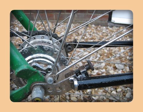
The only bad design point of the SON hub dynamo is the fact it uses crimp terminals as the interface to the outside world, YUK! So I came up with the idea of a small 'flying' cable with a Redel socket on the end so the front light or charger can be plugged in. This clips onto the front rack horizontal bar, & can be easily unclipped to deal with the inevitable punc$%!es.
-------------------------------------------------------------------------------------------------------------
Trailer hitch repair / improvement:
After the second aluminium hitch [horrible material!] broke on my Koolstop trailer it was time for some new ones. Also as I was never to keen on the original trailer arms, being so wide, I designed some new ones that would better suit the new hitches.

The original hitches, made from aluminium (yuk!). R.H one shows repair
using a steel plate screwed to the body via some drilled and taped holes.


The original hitches, made from aluminium (yuk!). R.H one shows repair
using a steel plate screwed to the body via some drilled and taped holes.

The trailer arm secures to the hitches by two spring-pins (not shown) that pass through the top holes.

The two arms, made from 3mm stainless. (templates were drawn
in autocad & then double-sided down to cut & drill).
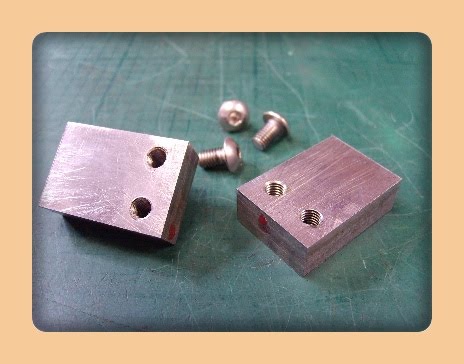
Main body of the hitch, cut from a length of ferrous steel, drilled & taped to bolt the arms into place.

Both parts married up.

Slots machined in for the trailer arm bolt / pins. (A few grams lost with 2 additional back holes).

Corners & edges rounded, then buffed up. (retaining screws also seen).

1.6mm steel tubes, bent by a friend who runs an engineering firm.

Reasonable time spent filing the ends to butt-up against respective faces for maximum weld contact, I had to make a small wooden jig so parts would stay put whilst welded (a friend’s colleague done the welding).

The 45' support arms took two attempts to make as the bottom face butts-up onto
the arms, just where the bends are & being proved awkward to machine & file.

These are the end caps, after drill & taping the M8 bolts would thread into.

The M8 bolts. Shanks were machined down to 7.5mm & one side of the nut taken off.
These screw into the new trailer arm caps, then drop in to the hitch slots when in use.

After a splash of Hammerite, Bobs ya' uncle.

Fitted & good to go. Thumb-screws were used for the retaining screws as proved quicker to fit the trailer.


Beats me why Koolstop made them so wide, and the hitches from aluminum?!
Seat post powered front & rear lights:
Touring bike 'top box':
Subscribe to:
Comments
(Atom)
